Transrapid - Guideway & Switching
Since the guideway carries the vehicle and provides the power
to the system, its precision design and fabrication are paramount
to the Transrapid technology. In addition, since overall system
ride comfort is directly related to the execution and quality
of the guideway, adherence to specifications and tolerances is
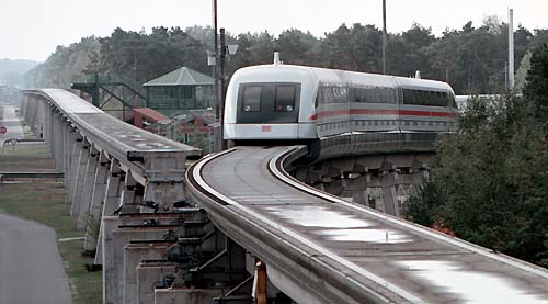
critical. Since the beginning of the operation of the Transrapid
Test Facility in Emsland, Germany (TVE) in 1984, eighteen different
types of guideway beams have been developed and tested. The design,
installation, testing, and refinement of these guideway beam
designs have led to the application beams in the Transrapid specifications.
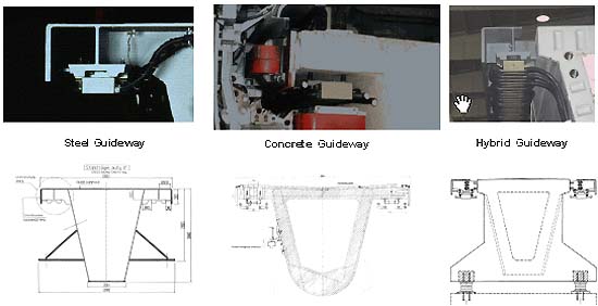
Guideway Material Types
The guideway beam, or girder, serves two important system
functions (1) to support the weight of the vehicle and
transfer the corresponding loads to the ground and (2) to provide
the apparatus for the mounting of the functional components.
Consequently, the guideway beams must be of a suitable stiffness
to maintain the system tolerances and must provide for the attachment
of the functional components (guidance rails, slide rails, stator
packs, motor windings, power rails, and vehicle location reference
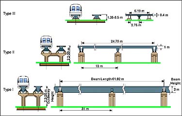
flags). These parameters have led to a standard-shaped guideway.
The 'trapezoid'-shaped box cross-section provides the beam strength,
while the functional components are mounted to the underside
of each cantilever element of the beam. The guideway beam design
allows for the flexibility of elevated, at-grade, bridge or tunnel
operations.
|
|
Switching
The Transrapid vehicle changes tracks using bending switches
or transfer tables. Bending switches are used in mainline and
off-line situations for smooth transition between tracks. They
consist of welded steel, multi-span, bending beams with electro-mechanical,
rack and pinion drive units mounted on every second support of
the bending switch. Locking mechanisms ensure the positioning
of the steel beam. Both low-speed and high-speed switches are
available for use on the Transrapid system. The low-speed switch,
typically used near stations and maintenance facilities, has a
total beam weight of 300 tons and a total beam length of 257 feet
(78 m). In the turnout position, speeds are restricted to 62 miles
per hour (100 km/h), while full operating speed is allowed in
the straight position. The high-speed switch, typically used on
a mainline portion of a system, has a weight of 600 tons and a
total beam length of 487 feet (148 m). It allows a turnout speed
of 124 miles per hour (200 km/h) and permits full speed in the
straight position. Bending switches are available in both two-way
(switching between two tracks) and three-way (switching between
three tracks) versions. The bending switches are designed for
a service life of approximately a million cycles, or twenty to
thirty years of typical service. One low-speed switch and two
high-speed switches are currently installed at the TVE.
Guideway Bending Switch:
|Transfer tables are used in off-line situations (e.g. maintenance
areas) for compact access of multiple tracks. They consist of
welded steel, multi-span, straight beams with electro-mechanical,
rack and pinion drive units mounted on every second support of
the transfer table. Locking mechanisms ensure the positioning
of the steel beam. With the vehicle resting on top, the transfer
table shifts laterally to access parallel segments of guideway.
Switch at Transrapid Test Facility
 / back to Maglev Monorail Page / back to Maglev Technical Home Page / back to Maglev Monorail Page / back to Maglev Technical Home Page
|